Also available as: PDF.
Model transformations and tool integration
Department of Computer Science, King’s College London, Strand, London, WC2R 2LS.
laurie@tratt.net
Abstract
Model transformations are increasingly recognised as being of significant importance to many areas of software development and integration. Recent attention on model transformations has particularly focused on the OMG’s Queries / Views / Transformations (QVT) Request for Proposals (RFP). In this paper I motivate the need for dedicated approaches to model transformations, particularly for the data involved in tool integration, outline the challenges involved, and then present a number of technologies and techniques which allow the construction of flexible, powerful and practical model transformations.
1 Introduction
In recent years the movement towards developing software with the use of models has increased rapidly. Organizations are increasingly seizing the opportunity to move their intellectual property and business logic from source code into models, allowing them to focus on the important aspects of their systems, which have traditionally been buried – and sometimes lost – in the mélange resulting from the use of standard programming languages. The introduction of models has opened up new possibilities for creating, analyzing, and manipulating systems through various types of tools. However the increasing availability of tools which operate on models has raised a new challenge: individual tools tend to only operate on models that conform to their own internal format, meaning that models created in one tool are rarely easily exportable to other tools. Not only have users found themselves locked into using their models with a single tool throughout the entire life-cycle, but the opportunity to harness the power and individual abilities of different tools as part of a tool chain has thus far been largely missed.
Model transformations are the key to solving this very fundamental problem, which also goes to the very heart of the OMG’s Model Driven Architecture (MDA) initiative [12, 23]. The existence of practical model transformation technologies will not only free users from tool lock-in, but more importantly facilitate the seamless transfer of models to and from specialized tools during the development life-cycle. A simple definition of a model transformation is that it is a program which mutates one model into another; in other words, something akin to a compiler. Of course, if this simple description accurately described model transformations, then we would be faced with a relatively simple and uninteresting problem to solve. In reality, model transformations are required to perform far more complex tasks – for example, when integrating tools it is frequently required that after an initial transformation of a model from one tool to another, subsequent changes are propagated in a non-destructive manner. Furthermore using standard programming languages and libraries to write even simple model transformations is a challenging, tedious and error-prone task. Model transformations need specialised support in several aspects in order to realise their full potential, for both the end-user and transformation developer.
In this paper I aim to give the reader a feel for the problem that model transformations are meant to solve, with particular emphasis on their applicability to the data involved in tool integration; the background and scope of model transformations including work related to the QVT RFP; finally I present a number of technologies and techniques which allow the construction of flexible, powerful and practical model transformations which can aid tool integration throughout the development life cycle.
1.1 Simple example
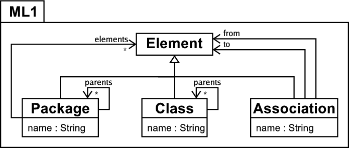
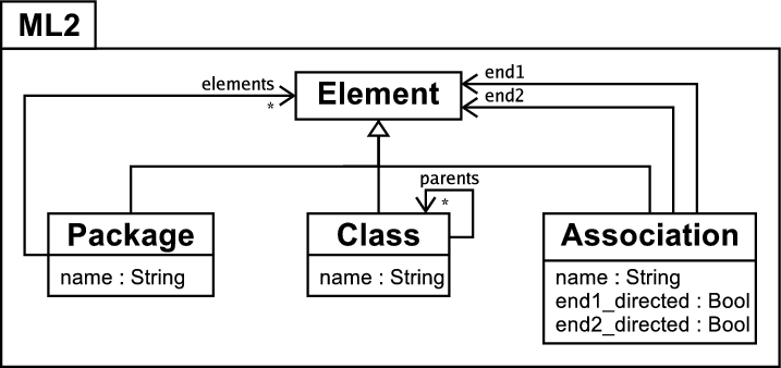
Figure 1 shows the metamodels of two similar modelling languages which will be used in most of the examples in this paper. In the interests of brevity I do not formally define the semantics of these languages, assuming that equivalent elements in either modelling language have the same semantics unless otherwise stated. The modelling language ML1 in figure 1(a) supports directed associations and package inheritance, a mechanism for structuring models – see [5] for an example of a modelling language with package inheritance. For the purposes of this example, a package A which inherits from a package B is considered to posses a copy of all the elements in B. Figure 1(b) shows the modelling language ML2, which does not provide support for package inheritance but allows undirected associations. Because of the large overlap between the two metamodels, many models can be instances of either metamodel; however some models will make use of theconflicting features of one or the other modelling language and are thus not directly interchangeable. This is very representative of the real world where two modelling tools store and manipulate models in only marginally different fashions, yet still end up preventing users from interchanging their models between them.
Figure 2(a) shows a typical example of package inheritance in a simple model of a company where different aspects of the company have been separated into separate packages to aid comprehension. The Company package then inherits the relevant sub-packages to create one package which contains all the relevant parts of the company model. Because this model makes use of package inheritance it can only be an instance of the ML1 modelling language. Thus any tool which understands the ML2 modelling language will not be able to interpret it correctly because of the package inheritance involved. Intuitively the solution is simple – the ML2 version of the model in figure 2(a) is one with all the relevant model elements copied down from the inherited packages. Figure 2(b) shows such a model created by hand (with redundant packages removed from the diagram in the interests of brevity). Since this is a tedious task, the problem is how to automate this process.
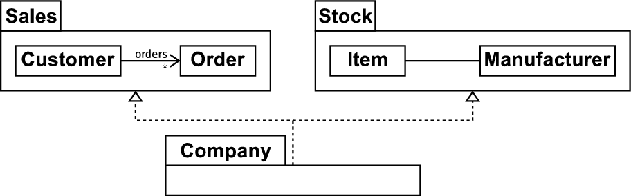
(a) Company model with package inheritance. |
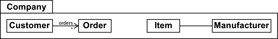
(b) Company model without package inheritance. |
Any first attempt at model transformations is likely to be in a standard programming language. A relatively, but not completely, naïve attempt, expressed in a fairly high-level pseudo-code, might look as follows1:
if type(element) == ML1.Package:
package_elements := []
for package_element in element.elements:
package_elements.append( \
transform(package_element))
parents_temp := element.parents.copy()
for parent in parents_temp:
for parent_element in parent.elements:
package_elements.append( \
transform(parent_element))
parents_temp.extend( \
parent_element.parents)
return new M2.Package(element.name, \
package_elements)
elif type(element) == ML1.Class:
parents := []
for parent in element.parents:
parents.append(transform(parent))
return new ML2.Class(element.name, parents))
elif type(element) == ML1.Association:
return new ML2.Association(element.name, \
transform(element.from), \
transform(element.to), true, false)
func main(model_in:Seq{ML1.Element}):Void:
model_out := []
for element in model_in:
model_out.append(transform(element))
The essential idea here is to transform every element that is an instance of the ML1 language into its counterpart in the ML2 language; elements from inherited packages are bought into the child packages and the package inheritance itself disappears. This approach has two immediate, and closely related, problems: elements can easily be duplicated during the transformation e.g. if a class S is specialized by two other classes then two copies of S will appear in the target model; cycles in the model created by associations between two classes cause the transformation to loop without terminating. A less concrete problem is that the transformation has been squeezed into one function, which grates against software engineering principles.
In order to overcome the flaws present in a relatively simple solution such as this, one has to add increasing amounts of machinery e.g. to keep track of which elements have already been transformed. Although space does not permit a detailed example, the necessary machinery for this and other such aspects, combined with the necessity for the machinery to pervade every aspect of the transformation, can quickly lead to the substance of the underlying transformation being swamped. This leads to the starting assumption for this, and most other, model transformation work: model transformations can not be sensibly written in a standard programming language, object orientated (OO) or otherwise.
1.2 Enabling a tool chain
In the previous section, I motivated the need for model transformations by exploring the need to perform a transformation between models stored in different tools, and the difficulties in trying to write such a transformation in a standard programming language. I classify the transformation example presented as a unidirectional stateless transformation. It is unidirectional because it can only transform an instance of ML1 into an instance of ML2. It is stateless because running the transformation when the source model has changed results in the creation of an entirely new target model even if it is an exact duplicate of the one that already exists. Although such a transformation can be of practical use in integrating together different tools, it tackles only part of the problem.
One enticing future scenario is when tools which specialize in different aspects of modelling can be used together throughout the development life cycle e.g. a UML modelling tool UT and a Java modelling tool JT. In such a scenario, a model is not just transformed between different tools once, but may be edited multiple times in each tool. For example, an initial model may be created in UT, transformed and subsequently edited in JT before high-level architectural changes are applied in UT which one expects to see reflected in JT. A similar, although more linear, scenario involving incremental model development is explained in Becker et. al [8]. The general aim underlying such scenarios is to allow the user to leverage different tools specialities at varying points in the development life cycle.
It is important to note that the scenario given here is deliberately limited compared to the general case. It calls only for changes in UT to be propagated to JT, not vice versa. A solution for the general case would utilize a bidirectional transformation that could also propagate any relevant changes made in JT to UT. True bidirectional transformations present a number of challenges above and beyond those tackled in this paper, and by most current model transformation technologies, and are consequently largely ignored in this paper – however all of the challenges listed here apply equally to bidirectional transformations.
The significant challenge raised by this scenario can be seen in figure 3. Imagine we have the model in figure 3(a), an instance of the ML2 modelling language, in a tool MT2, and then transform it into an instance of the ML1 modelling language for use in another tool MT1. The result of the transformation from ML2 to ML1 is shown in figure 3(b), which contains two directed associations. Now if the user changes the model in MT2, what might the result be on the model in MT1? The example presented in the previous section would simply wipe whatever was in MT1 and create an entirely fresh model. This might be acceptable in some very limited circumstances, but not if one has added extra detail into the model in MT1 which must not be wiped, as in the UT and JT example.
A more sophisticated approach would be for the transformation to attempt to perform the minimum alteration to the target model to propagate the changes, leaving it otherwise intact. In order to do this, the transformation needs to somehow recognise those elements in the model in MT2 which relate to those in MT1 and use, or change, them appropriately. This initially seems fairly trivial – for example the Employee class is obviously shared in both models. However, consider the bidirectional association in MT2 which is non-trivially related to two directed associations in MT1 – how should a transformation recognise such a relationship? One could discover in an MT2 model a pair of directed associations which because of their names appear to correspond to a bidirectional association in MT1, but such correspondences may be pure coincidence (the user being free to name associations as they so wish), which would lead to an incorrect change propagation. In fact, no matter how clever such a calculation might be to avoid such problems, one significant problem is that the deletion of an element in MT2 should result in the appropriate deletion of elements in MT1 – however if the transformation has no record of which elements in MT2 relate to those in MT1 it will be unable to perform such a deletion reliably.
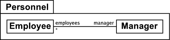
(a) The Personnel package in the ML2 language. |
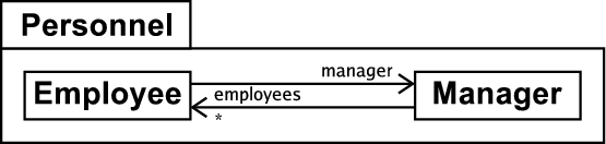
(b) The Personnel package in the ML1 language. |
One can see from these problems that the problem of change propagation is harder than first imagined. At a minimum, it seems that information needs to be kept about which elements are related to which by a transformation – this is typically called tracing information. I classify a transformation which can record and utilise such information to propagate changes as a persistent transformation. However this is not only part of the required solution as shall be seen in section 3.5.
1.3 A method for model transformations
Based on examples, such as those just presented, a simple method for model transformations can be discerned which can significantly aid understanding of the general problem and also allows the comparison of different approaches by describing where, and how well, any approach fits into the method. Because, as shall be seen in chapter 2, model transformations come in various different flavours, this method is intentionally high level and therefore applicable to the majority of practical approaches. For example, in a simplistic approach encoded in an OO language this method would apply to the entire program; in a rule based approach, this method can be seen to apply to each rule. The example in figure 4 is intended to help visualise these parts:
- Searching a model to identify appropriate elements transform.
- Transforming elements.
- The retention (in some manner) of tracing information recording which elements in a model are related by the transformation to elements in other models.
- Detecting updates in one model involved in the transformation and performing relevant operations in the transformations other affected models.
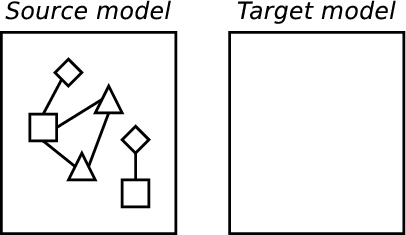
(a) Initial model. |
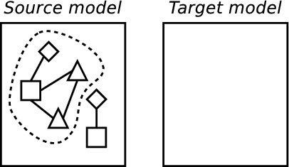
(b) Identifying elements. |
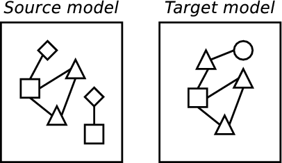
(c) Transforming. |
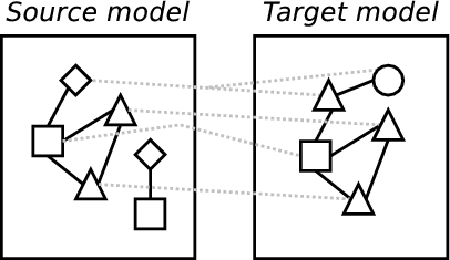
(d) Creating tracing information. |
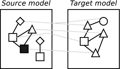
(e) Altering a model. |
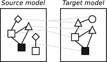
(f) Propagating changes. |
Whilst a minimal approach to model transformations need only perform parts one and two, a complete approach would be capable of performing all parts: a model transformation technology which limits itself to merely taking in one model and spiting another model out fails to tackle all the problems relevant to tool integration outlined in section 1.2. However, although the method comprises four main parts, it is not necessary for these parts to correspond to distinct phases of execution. Parts one and two are often partially intertwined and it would be surprising if parts two and three in particular were implemented as separate phases because the required information for part three will be determined by what happens in part two.
2 Background
2.1 Program transformations
Transformations in a computing context are far from a new idea, cropping up in many contexts, in more or less formal ways. For example, compilers are effectively program transformations which (hopefully) preserve the semantics2 of the input source code when they transform it into the output binary. Literature available for specific types of program transformation such as compilation and optimization abound, from practical guides (e.g. the classic ‘dragon book’ [2]) to theoretical work on the validity of applying such transformations (e.g. [32] which gives a condensed history of compiler transformation proofs before presenting state of the art work in the field).
Program transformations are typically unidirectional stateless transformations, and deal with a restricted subject area. Model transformations encompass a much wider scope (see e.g. [12, 23]).
2.2 XSLT
XSLT [48] is an XML transformation technology which has gained a significant amount of attention over the past few years. XSLT initially seems a promising candidate in which to realise model transformations, because representing models in XML is a common exercise. As noted in Bex et al. [10], ‘XSLT is highly adequate for the simple transformations it was intended for (recall that XSL was originally intended just for XML to HTML transformations)’ but has serious shortcomings for more advanced transformations. Interestingly it took several years before a formal proof was constructed that XSLT is Turing complete [30]3 and – as both the relatively recent timing and need for existence of the proof may suggest – in practical usages one quickly hits the limits as to the sorts of transformations XSLT can naturally express. Peltier et al. [38] consigned XSLT to the lowest-level of their MTRANS model transformation framework, citing general readability issues as well as specifics such as the lack of acceptable error reporting.
A final issue which makes expressing model transformations in XSLT less than ideal is that XML documents are represented as a tree structure; models are, in the general case, naturally representable as graphs. Although graphs can be represented by trees with link references between nodes, the difference in representation can lead to an unnatural representation of many types of model transformations.
2.3 Graph transformations
A particular type of transformation which has gained a lot of traction in theoretical circles since their introduction in the late 60’s are graph transformations (see [4]). Note that the term ‘graph transformation’ is potentially misleading, since in this context it is used to refer to a particular category of rule-based transformations that are typically represented diagrammatically; various other types of transformations operate on graphs but are not termed ‘graph transformations’. Graph transformations have a number of attractive theoretical properties, and for our purposes the fact that models are well represented as graphs is particularly appealing.
Early work involving graph transformation and models largely centred on their use in defining the semantics of different modelling diagram types, such as the continuing work of Gogolla et al. [25, 24, 26]. More recent work by Küster et al. [31] has defined a more general model transformation approach using graph transformation as the underlying mechanism, allowing them to draw upon some of the properties of graph transformations in a model transformation context. Heckel et al. [28] have continued this work, reasoning about confluence with typed attributed graphs. [15, 34, 41, 47, 51] have all proposed model transformation approaches which are essentially based upon simplified views of graph transformations, as is Agrawal et. al’s more mature GReAT system [1].
Although graph transformations can be used to prove interesting properties about transformations, only a fairly small minority of useful transformations are currently amenable to such analysis thus reducing the usefulness of such analysis in practical situations. Most of the graph transformation approaches detailed in this section give little or no attention to mechanisms for structuring graph transformation systems despite the fact that large graph transformation systems appear to need such mechanisms as much as large procedural programs (see [40] for an example of a structuring mechanism based on UML packages for a graph transformation system). Partly because of this lack of structuring mechanisms, solutions based on the graph transformation paradigm are often perceived by users to be complex beasts [19] and hence have seen relatively little real-world usage. Few graph transformation based systems support change propagation; Becker et. al [8] is one of the few to provide slightly limited support for this important aspect of model transformations.
2.4 Other approaches
Various stand alone works have been published on model transformations that are not covered elsewhere in this paper. Two of the first works in the area are that of Lano [33] and Evans [21] who both define transformations with respect to an underlying semantics of class diagrams. In both cases these transformations are not directly executable: such work can therefore be seen as specifying model transformations. Later work such as that of the 2U group [16] and Akehurst and Kent [3] refine the use of class diagrams and OCL for transformation specifications. More recent work has concentrated on executability, such as that of as Whittle [50] who used the logic programming language Maude to execute and verify simple transformations.
2.5 QVT
Model transformations are a vital factor in the realization of the OMG’s MDA vision [12], which is based on the idea of progressively facilitating more and more software development with models. Implicit in this vision is that models will need to be manipulated into various different forms. For example: transforming models representing one technology into others which represent different technologies; abstracting and refining models; merging models; and so on. To this end a Request For Proposals (RFP) was issued by the OMG ‘MOF 2.0 Queries / Views / Transformations (QVT)’ [35] in 2002 to seek a standard way of performing model transformations.
There were eight initial submissions to the RFP; at the time of initial writing seven remain. This paper is not intended to enumerate the individual submissions; see Gardner et al. [22], and Czarnecki and Helsen [19] who propose a detailed classification scheme for transformation approaches.
The following sections first detail two important points at the extreme of the QVT spectrum before briefly enumerating other related approaches which fall in between the two.
2.5.1 TRL
The Transformation Rule Language (TRL) language [37] is in essence a standard rule-based imperative language specialized for UML-esque model transformations. This comes in several forms: concepts such as ‘transformation rule’ are raised to first-class status; some of the information recorded in the new first class elements is used for additional purposes e.g. to create tracing information; extra syntax is provided for e.g. accessing the stereotype of a UML model element. Rules consist of a crude signature (comprising the types of the source and target model elements) and an imperative body. The syntax and semantics of actions are essentially that of the Object Constraint Language (OCL) [36] augmented with side-effects and a small handful of necessary control structures.
The benefit of such an approach is its relative familiarity to users, and the knowledge that largely imperative solutions traditionally lead to efficient implementations. However TRL is only capable of expressing unidirectional stateless transformations, due to the imperative nature of rule actions.
2.5.2 xMOF
The xMOF language [17] is a constraint solving model transformation system aiming to declaratively specify persistent bidirectional transformations. An xMOF program consists of a number of OCL constraints about model elements involved in a transformation. The declarative approach taken aims to rid the implementer of the tedious and verbose book-keeping inherent in imperative approaches. Also, because the relationship between two models need not be stated in terms of inputs and outputs, the transformation is potentially bi-directional, and change propagation can also be handled automatically, as a change in one model will cause constraints on another to fail bringing the xMOF engine into life.
This approach has several severe disadvantages from a practical standpoint. For example it places a burden on the user to ensure that the constraints specified completely describe the transformation – failure to do so will result in a system which produces arbitrary results,or runs out of memory as it attempts to enumerate all matching values. Due to the complex interaction between constraints, it is arguably easier in a constraint solving situation to create a non-terminating program than in other paradigms.
Significantly, constraint solving systems easily lead to solutions which can take potentially unbounded time to execute. Constraint programming, as detailed by e.g. Barták [7] is a challenging and relatively unexplored area of research (despite existing for over four decades [43]), which has shown potential in small, tightly defined areas, but there is little precedent for using it on a task of the order of complexity of model transformations.
2.5.3 Other approaches
The DSTC QVT submission [20] is a declarative solution which can specify unidirectional persistent transformations, although it is unclear how the tracing information it creates is used for propagating changes.
The QVT-Partners – of whom the author is a member – submission [39] is a hybrid solution which offers declarative specifications and imperative implementations. Although the solution can automatically create tracing information, the largely imperative nature of implementations complicates change propagation (but see [44] for a suggested solution).
Bézivin et al.’s ATL [11] wraps imperative bodies inside declarative shells to specify unidirectional transformations; the imperative aspects are less important than in other ‘hybrid’ approaches such as that of the QVT-Partners.
2.6 Summary of existing approaches
The majority of current model transformations can be categorised as declarative. This is the result of a simple observation: in an imperative model transformation approach, such as TRL, one explicitly creates new elements in the target model, which effectively rules out the ability to propagate changes. Rather than explicitly creating and altering elements, declarative solutions instead assert their existence and state. So if an assertion about the existence of an element is made, and such an element doesn’t exist, it is created by the engine; otherwise the existing element is left as is. Importantly no duplicates are created in such a situation; alterations to elements are performed in a similar manner. This method works well for both initial transformations and for subsequent updates, as from the transformations viewpoint there is no discernible difference between an empty target model and one that already contains elements from a previous transformation.
At this point, it is important to note that although the above text uses ‘declarative’ and ‘imperative’ with the suggestion that only a fully declarative solution is capable of providing a practical solution to persistent model transformations, this is not in fact the case. The only aspect of any solution that needs to be declarative is that which deals with the relationship between elements in the source and target models. However the only solutions which are currently capable of doing this are those where the entire computation is specified declaratively. This is despite the fact that the details of the computation which leads to the declaration of a relationship between source and target model elements is irrelevant to the declaration itself.
3 Technologies and techniques for model transformations
The previous section concluded with the observation that most current model transformation approaches can be classified as declarative. The purpose behind much, though not all, of the work in this paper was to develop appropriate technologies for performing model transformations in a largely imperative framework, such that change propagation is still feasible. The reason for this is no more complicated than a simple wish to explore a yet as untried approach to model transformations; since we are still in the beginning stages of this exciting area, exploring as many approaches as possible seems the best way to discover the most appropriate approaches.
This section presents work that draws upon the QVT-Partners submission and is implemented partly by, and partly in, the Converge programming language [45] (which has been developed to provide a flexible workbench for experimentation of this sort). Together, the technologies and techniques in this section provide a basis for creating unidirectional persistent transformations. After motivation and explanation of the individual technologies and techniques, section 3.5.1 presents an example of a transformation that shows how the different parts form a coherent whole.
3.1 Imperative language with backtracking
Converge is an imperative language, syntactically similar to Python [46] with semantics heavily inspired by those of Icon [27]. In essence it is a strongly, dynamically typed, expression based, imperative language.
One of the chief problems with standard imperative approaches comes when identifying elements. Frequently arbitrary levels of backtracking are required in such identification; it is also generally required that model element access and storage are minimised due to the relative expensive of such operations in terms of time and space, particularly when a model repository is used. In standard imperative approaches, one typically faces prohibitively large amounts of book-keeping to implement the necessary backtracking (see section 1.1) even before the problem of minimizing model element access is considered. Converge solves this by utilizing Icon-esque resumable functions (known as generators in Icon) which can produce more than one return value over multiple invocations; these reduce the book-keeping necessary when iterating over models, provide lazy evaluation of model elements, and also allow for the trivial expression of a limited form of automatic backtracking.
A simple example of this important feature is as follows. Imagine we have a method on a model get_classes() which successively generates all the classes in a model, and another method is_leaf_class(c) which only succeeds if c is not generalized by any other classes. In Converge one can print all non-abstract leaf classes as follows:
In essence, the & operator joins expressions to allow backtracking to happen amongst them. In this scenario, the get_classes method generates a class, and assigns it to a. If the is_leaf_class method then fails when passed a, backtracking occurs and get_classes is resumed to generate another class. If it succeeds, the class is then tested to see if it is abstract. If it is not, control backtracks to the last generator (the get_classes call); otherwise the value of a is passed to the Sys.writeln method to print the class to screen. The for statement continues resuming the get_classes generator until it is exhausted.
3.2 An extensible language
Most programming languages, and most model transformation languages, are fixed in the sense that one can not add to their feature set. This often leads to the creation of small domain specific languages that might have fared better if the specific features had been embedded in a more general purpose language – a Domain Specific Embedded Language (DSEL) [29]. Since as stated earlier, there is no consensus as to which is the best approach for model transformations – if indeed one approach will ever satisfactorily cover all possibilities – it seems prudent to build model transformation languages that are capable of being arbitrarily extended by the user. Converge allows compile time meta-programming [18] that is heavily influenced by that of Template Haskell [42]. As seen in the example on page §, this allows arbitrary transformation approaches to be tried within a common framework, either separately or in conjunction with one another.
3.3 Rule based approach
One of the many reasons why the example in section 1.1 can be considered a failure is the tight coupling between the different sub-parts of the transformation encoded via multiple if statements. Even moving code into separate functions would still require altering one central piece of code when a new concept is introduced into the transformation. A more practical approach is that taken by rule-based languages (e.g. ELAN [14]), which allow one to define multiple independent rules of the form guard => action . At runtime, rules are fired depending on their guard not, as in more traditional languages, based on the name of the rule.
One problem sometimes encountered in rule based approaches is that a given piece of data can match several rules. At this point, use is made of rules relative precedences, which are often based on the order of their definition. However, transformations sometimes request the transformation of a chunk of data knowing which of several possible rules they would prefer to be executed. I therefore also assign names to rules, and allow rules to be explicitly invoked with the caveat that the data passed to any such rule must still satisfy its guard.
Having named rules also opens up the potential for interesting approaches to transformation composition – the combining together of individual model transformations. Out of the approaches discussed in this paper, only that of the QVT-Partners makes a serious attempt at composing transformations by means of operators such as or and and. Composition raises a number of interesting questions, particularly when used to merge the results of two or more model transformations together as in the QVT-Partners and composition. Hitherto there has been little exploration of the consequences of this. It seems likely that work in the aspect orientation community, such as that of Bergmans and Aksit [9], will offer pointers to scalable approaches to composition.
3.4 Pattern matching
A useful technique when specifying transformations is to use patterns [6]. Patterns in this context should be seen as being analogous to textual regular expressions as found in e.g. Perl [49], or the patterns work of Biggerstaff [13] – they are a concise way of expressing many types of constraints on items, generally through the use of a specific pattern language. Patterns are thus not a novel technique and have proved themselves in the field as a practical means of expressing transformations.
Since this may be an unfamiliar concept to some readers, a simple example of a pattern language expressed in the default that comes with Converge:
This particular model pattern is a simple object pattern, and will match successfully against an instance of the Package model element. The name of the package can be any value and will be assigned to the variable n. The object pattern contains a set pattern for the parents slot. This will only match successfully against a set which contains a minimum of one object, which must be an instance of the Package model element whose literal name is "Personnel"; all other elements of the set will be assigned to P. In other words, this pattern will match against any package which generalizes Personnel. Compare this with the far more verbose imperative code, or OCL constraints, required to specify what this pattern states.
Pattern languages typically have two main problems: due to the trade off between brevity and expressivity, they are generally not computationally complete; different types of pattern languages are useful in different circumstances. The first problem is relatively easily solved by intermixing arbitrary computations in the host language with patterns. The second problem is solved by not making any particular pattern language a fundamental part of the host language, but utilizing the support for DSEL creation to allow users to provide their own pattern languages if appropriate.
3.5 Change propagation
Practical approaches to change propagation are vital to the success of model transformations, particularly in the area of tool integration. Few approaches currently make a serious effort to tackle the problem. For example, Braun and Marschall [15] suggest that bijective transformations are sufficient to solve this problem, which is of limited practical use as many useful transformations, such as the ML1 to ML2 transformation, can never possibly be injective (and hence are not bijective). Similarly, simply creating tracing information, as in TRL, is no guarantee of the ability to propagate changes.
The approach I have developed allows the creation of unidirectional persistent transformations, with an algorithm which is capable of propagating simple types of change. Change propagation is an inherently difficult area, particularly in corner cases where one can usually find examples which will cause an algorithm to produce sub-optimal results. The challenge is to provide a solution which works well for most common scenarios. In essence the approach is based on a combination of tracing information and the calculation of unique identifiers to determine which target elements relate to which source elements.
Tracing information is automatically created and stored, utilizing the fact that transformation rules are classes whose instances can serialize themselves in a manner suitable for the particular environment they are operating within. This is important for tools, where transformations may be required to persist in memory at some points for efficiency reasons, and at others to be serialized to disk e.g. to be transferred to a different machine.
Elements in the output model are assigned identifiers based on the identifiers of the set of objects in the source model that were transformed; this calculation on an unchanged model should always return an identical result. For example a source element whose identifier is p, and which is referenced through an element whose identifier is a, will generate an output element identifier of the form a:p. This scheme allows the same source element to be involved in different parts of the transformation whilst still leading to a unique output identifier in each situation. For example in the same transformation p might be referenced through b and then c which will generate an identifier of the form b:c:p. Note that it is necessary to have a convention for ensuring unique identifiers in certain contexts e.g. a for loop.
When a change is to be propagated from the source to the target model, the basic algorithm is as follows. The transformation is effectively rerun from scratch, with the unique identifiers generated by source model elements used as part of the declarative specification of the existence or state of target model elements. At the same time, a new set of tracing information is created. The new tracing information is then compared to the old, and any target model element referenced in the old tracing information but not in the new is then deleted. The precise effect of such deletion is determined by the particular change propagation algorithm, and is currently fairly simplistic; the element and pointers to it within any elements are removed.
Although most changes are propagated successfully, certain changes in the source model can lead to an excessively inefficient propagation stage or to an ill-formed target model; currently this is not correctly detected, although such detection appears to be possible and feasible. A direct analogy to source code revision systems such as CVS can be drawn here. In such systems, the vast majority of changes which users make to files integrate into the repository correctly. However in some situations the system is unable to automatically reconcile overlapping changes made by two developers and has to request the users aid in resolving the conflict. A similar need is found in model transformations, although currently it is under explored.
3.5.1 Example
I now present an example of a simple transformation rule which transforms ML1 packages to ML2 packages – the most complex aspect of the transformation in section 1.1,– in Converge. This example shows the technologies and techniques presented in the previous sections working in conjunction with one another.
class Package_To_Package of \
ModTr.Transformation_Class:
$ModTr.transformation():
source_pattern := \
"(ML1.Package)[name=<n>, parents=<p>, \
elements=<e>]"
target_pattern := "(ML2.Package)[name=n, \
elements=ne]"
func target_where():
ne := e
for parent in p:
parent := ModTr.transform(p)
for element in parent.elements:
ne.assert_existence(element)
A full explanation of this is quite involved; however some aspects in particular need explanation. As Converge has a Python style syntax, blocks are synonymous with indentation. The ModTr package contains a number of transformation related components which are imported wholesale by the transformation, and which together constitute a DSEL for model transformations – a completely separate package could be created which implemented a partially or entirely different DSEL if required, since none of the transformation features are built directly into the language.
The $ operator introduces a ‘macro splice’; the transformation call after it means that the named function will be called at compile time with the three fields source_pattern, target_pattern and target_where passed in a dictionary as a final parameter. These three fields have as their values the abstract syntax tree of the text above4. The source and target patterns, and their associated source_when and target_where functions, form the core of generated routines which identify and create or alter elements. Having analysed the source and target patterns for free and for bound (variables between triangular brackets) variables, the transformation function then transparently alters the target_where function so that the e variable from the source pattern is present in the function, and also that the final value of the ne variable is positioned correctly in the target pattern.
The overall result of the macro splice is to transform the fields above, at compile time, into an efficient transformation rule. The generated code is larger, and considerably more complex, than the relatively simple code above. The complexity is due to the resulting transformation being persistent, and capable of propagating changes. Most of the machinery responsible for this is generated from the source and target patterns and is thus largely invisible to the user. However, the user must, when writing code in the standard imperative language, adhere to certain rules; an example can be seen in the target_where function with the call to the assert_existence which ensures that element is present in the set ne without explicitly altering ne itself. Importantly the user must not explicitly alter the target model.
The final piece of the puzzle is the of keyword, which signifies that the Package_To_Package class is an instance of the Transformation_Class class; one side effect of this in the simple ModTr DSEL is to automatically register the transformation rule with the engine. When the ModTr.transform function is called, all relevant transformation rules are called, with overlaps in rule guards being resolved in favour of rule definition order.
In summary, what the example shows is an transformation in an imperative language which by utilizing a DSEL for model transformations allows persistent transformations in a rule-based style to be created by forcing the relations between models to be specified declaratively, but not the rest of the computation. Transformations of this sort fulfil the requirements for tool integration as outlined in section 1.2.
4 Future work
We are still very much in the beginning stages of creating appropriate technologies for model transformations. It is far too early to decisively conclude which of many different approaches, if any, is the most promising. Therefore one of the main challenges for the community is simply to continue exploring different approaches to model transformations. This paper has attempted to aid in this by exploring an imperative solution that allows declarations between models via DSELs. Many other challenges remain, for example: what are useful types of transformation composition? How frequently do changes in a persistent transformation need to be propagated to ensure consistent models and efficient execution, and is it possible to minimise the proportion of the transformation that is rerun? What are appropriate algorithms for change propagation and how does one resolve conflicts? We have partial answers for some of these questions, but many remain largely unanswered.
In terms of the particular approach presented in this paper, two main challenges remain. One is to continue work on a production quality implementation. Currently the bootstrap version of Converge is finished and allows reasonable experimentation but is too slow for most practical purposes. A much faster, scalable version is nearing completion. This will allow the completion of the bootstrap compiler; currently the DSEL facilities are hard coded into the compiler rather than calling user code. The second main challenge is to continue writing transformations, noting any problems and extending or modifying the approach as appropriate. Model transformations are an inherently practical task, with most real progress coming from practical experience.
5 Conclusions
In this paper I have given an overview of model transformations, and outlined how they can play a critical rôle in enabling tool integration. Persistent model transformations were shown to allow advanced usage scenarios that are currently largely unfeasible. I then presented a review of current model transformation approaches that identified common weaknesses and unexplored avenues. Based on this I then identified a new approach to model transformations that is capable of providing a flexible, efficient, and practical platform for creating model transformations that facilitate advanced tool integration. By utilising an imperative paradigm capable of backtracking, and allowing user specified transformation DSEL’s to handle declarative aspects, I demonstrated that this approach provides not only a solid framework in which to carry out continued experimentation, but also a practical means of performing model transformations in circumstances that do not necessarily need to have been considered during the languages initial design.
I would particularly like to thank Tony Clark for his advice and encouragement over the past few years and for his reading of an early draft; Girish Maskeri also provided insightful comments on an earlier draft. I would also like to thank the anonymous referees whose comments helped improve the presentation of this paper markedly.
This research was partly funded by a grant from Tata Consultancy Services.
References
[1] A. Agrawal, G. Karsai, and F. Shi. Graph transformations on domain-specific models. Technical report, Institute for Software Integrated Systems, Vanderbilt University, November 2003.
[2] A. V. Aho, R. Sethi, and J. D. Ullman. Compilers: Principles, Techniques and Tools. Addison Wesley, 1986.
[3] D. H. Akehurst and S. J. H. Kent. A relational approach to defining transformations in a metamodel. In J.-M. Jézéquel, H. Hussmann, and S. Cook, editors, UML 2002 – The Unified Modeling Language : 5th International Conference, pages 243 – 258. Springer-Verlag, 2002.
[4] M. Andries, G. Engels, A. Habel, B. Hoffmann, H.-J. Kreowski, S. Kuske, D. Plump, A. Schürr, and G. Taentzer. Graph transformation for specification and programming. Technical Report 7, University of Bremen, 1999.
[5] B. Appukuttan, T. Clark, A. Evans, S. Kent, G. Maskeri, P. Sammut, L. Tratt, and J. S. Willans. Unambiguous uml submission to uml 2 infrastructure rfp, September 2002. OMG document ad/2002-06-14.
[6] B. K. Appukuttan, T. Clark, S. Reddy, L. Tratt, and R. Venkatesh. A pattern based model driven approach to model transformations, November 2003. Metamodelling for MDA 2003.
[7] R. Barták. Constraint programming: What is behind? In Proceedings of CPDC99, pages 7 – 15, June 1999.
[8] S. M. Becker, T. Haase, and B. Westfechtel. Model-based a-posteriori integration of engineering tools for incremental development processes. SoSYM, 2004. To appear.
[9] L. M. Bergmans and M. Aksit. How to deal with encapsulation in aspect-orientation. In Proceedings of OOPSLA 2001 Workshop on Advanced Separation of Concerns in Object-Oriented Systems, October 2001.
[10] G. J. Bex, S. Maneth, and F. Neven. A formal model for an expressive fragment of XSLT. Information Systems, 28(1):21–39, 2002.
[11] J. Bézivin, G. Dupé, F. Jouault, G. Pitette, and J. E. Rougui. First experiments with the ATL model transformation language: Transforming XSLT into XQuery. In 2nd OOPSLA Workshop on Generative Techniques in the context of Model Driven Architecture, October 2003.
[12] J. Bézivin and S. Gérard. A preliminary identification of MDA components. In Generative Techniques in the context of Model Driven Architecture, Nov 2002.
[13] T. J. Biggerstaff. Pattern matching for program generation: A user manual. Technical Report TR-98-55, Microsoft Research, 1995.
[14] P. Borovanský, C. Kirchner, H. Kirchner, P.-E. Moreau, and M. Vittek. Elan: A logical framework based on computational systems. In Proc. first international workshop on rewriting logic, 1996.
[15] P. Braun and F. Marschall. Transforming object oriented models with BOTL. International Workshop on Graph Transformation and Visual Modeling Techniques, 72(3), 2002.
[16] T. Clark, A. Evans, and S. Kent. Initial submission to OMG RFP’s ad/00-09-01 (UML 2.0 infrastructure) ad/00-09-03 (UML 2.0 OCL), 2001.
[17] Compuware and Sun. XMOF queries, views and transformations on models using MOF, OCL and patterns, August 2003. OMG document ad/2003-08-07.
[18] K. Czarnecki and U. W. Eisenecker. Generative Programming. Addison Wesley, 2000.
[19] K. Czarnecki and S. Helsen. Classification of model transformation approaches. In J. Bettin, G. van Emde Boas, A. Agrawal, E. Willink, and J. Bézivin, editors, Second Workshop on Generative Techniques in the context of Model Driven Architecture, October 2003.
[20] DSTC, IBM, and CBOP. MOF query / views / transformations first revised submission, August 2003. OMG document ad/2003-08-03.
[21] A. Evans. Reasoning with UML class diagrams. In Second IEEE Workshop on Industrial Strength Formal Specification Techniques, October 1998.
[22] T. Gardner, C. Griffin, J. Koehler, and R. Hauser. Query / views / transformations submissions & recommendations towards final standard, August 2003. OMG document ad/03-08-02.
[23] A. Gerber, M. Lawley, K. Raymond, J. Steel, and A. Wood. Transformation: The missing link of MDA. In A. Corradini, H. Ehrig, H.-J. Kreowski, and G. Rozenberg, editors, Graph Transformation: First International Conference, ICGT 2002, pages 90–105, October 2002.
[24] M. Gogolla. Graph transformations on the UML metamodel. In J. D. P. Rolim, A. Z. Broder, A. Corradini, R. Gorrieri, R. Heckel, J. Hromkovic, U. Vaccaro, and J. B. Wells, editors, ICALP Workshop on Graph Transformations and Visual Modeling Techniques, pages 359–371. Carleton Scientific, 2000.
[25] M. Gogolla and F. Parisi-Presicce. State diagrams in UML: A formal semantics using graph transformations. In M. Broy, D. Coleman, T. S. E. Maibaum, and B. Rumpe, editors, Proceedings PSMT’98 Workshop on Precise Semantics for Modeling Techniques. Technische Universität München, TUM-I9803, 1998.
[26] M. Gogolla, P. Ziemann, and S. Kuske. Towards an integrated graph based semantics for UML. In P. Bottoni and M. Minas, editors, Proc. Int. Workshop on Graph Transformation and Visual Modeling Techniques (GT-VMT 2002), volume 72 of Electronic Notes in Theoretical Computer Science, 2003.
[27] R. E. Griswold and M. T. Griswold. The Icon Programming Language. Peer-to-Peer Communications, third edition, 1996.
[28] R. Heckel, J. M. Küster, and G. Taentzer. Confluence of typed attributed graph transformation systems. In A. Corradini and H.-J. Kreowski, editors, Proceedings First International Conference on Graph Transformation (ICGT 02), pages 161 – 176. Springer-Verlag, October 2002.
[29] P. Hudak. Building domain-specific embedded languages. ACM Computing Surveys, 28(4), December 1996.
[30] S. Kepser. A proof of the Turing-completeness of XSLT and XQuery. Technical Report SFB 441, Eberhard Karls Universität Tübingen, June 2002.
[31] J. M. Küster, R. Heckel, and G. Engels. Defining and validating transformations of UML models. In IEEE Symposium on Visual Languages and Formal Methods, October 2003.
[32] D. Lacey, N. D. Jones, E. V. Wyk, and C. C. Frederiksen. Proving correctness of compiler optimizations by temporal logic. In Proc. 29th ACM Symposium on Principles of Programming Languages, pages 283–294. Association of Computing Machinery, 2002.
[33] K. Lano and J. Bicarregui. UML refinement and abstraction transformations. In Second Workshop on Rigorous Object Oriented Methods: ROOM 2, Bradford, May 1998.
[34] T. Levendovszky, G. Karsai, M. Maroti, A. Ledeczi, and H. Charaf. Model reuse with metamodel-based transformations. In C. Gacek, editor, ICSR, volume 2319 of Lecture Notes in Computer Science. Springer, 2002.
[35] Object Management Group. Request for Proposal: MOF 2.0 Query / Views / Transformations RFP, 2002. OMG document ad/2002-04-10.
[36] Object constraint language specification, 1997. OMG document ad/97-08-08.
[37] OpenQVT. Response to the MOF 2.0 query / views / transformations RFP, August 2003. OMG document ad/2003-08-05.
[38] M. Peltier, J. Bézivin, and G. Guillaume. MTRANS: A general framework, based on XSLT, for model transformations. In WTUML 2001, Italy, April 2001.
[39] QVT-Partners. First revised submission to QVT RFP, August 2003. OMG document ad/03-08-08.
[40] A. Schürr and A. J. Winter. UML packages for programmed graph rewriting systems. In Proc. TAGT’98 - Theory and Application of Graph Transformations, November 1998.
[41] S. Sendall. Combining generative and graph transformation techniques for model transformation: An effective alliance? In Generative techniques in the context of MDA, October 2003.
[42] T. Sheard and S. P. Jones. Template meta-programming for Haskell. In Proceedings of the Haskell workshop 2002. ACM, 2002.
[43] I. Sutherland. Sketchpad: a man–machine graphical communication system. In Proceedings Spring Joint Computer Conference, IFIPS, pages 329–346, 1963.
[44] L. Tratt and T. Clark. Issues surrounding model consistency and QVT. Technical Report TR-03-08, Department of Computer Science, King’s College London, December 2003.
[45] L. Tratt and T. Clark. Model transformations in Converge, October 2003. Workshop in Software Model Engineering (WiSME) 2003.
[46] G. van Rossum. Python 2.2 reference manual, 2001. http://www.python.org/doc/2.2/ref/ref.html.
[47] D. Varró and A. Pataricza. UML action semantics for model transformation systems. Periodica Politechnica, 2003.
[48] W3C. XSL Transformations (XSLT), 1999. http://www.w3.org/TR/xslt.
[49] L. Wall, T. Christiansen, and J. Orwant. Programming Perl. O’Reilly, third edition, 2000.
[50] J. Whittle. Transformations and software modeling languages: Automating transformations in UML. In J.-M. Jézéquel, H. Hussmann, and S. Cook, editors, UML 2002 – The Unified Modeling Language : 5th International Conference, pages 227 – 242. Springer-Verlag, 2002.
[51] E. D. Willink. UMLX : A graphical transformation language for MDA. In 2nd OOPSLA Workshop on Generative Techniques in the context of Model Driven Architecture, October 2003.